![[UW Logo]](http://www.uwaterloo.ca/images/UWlogo.GIF)
This tutorial is supplemental - for interest only.
There are two verilog sources files and a screendump to look at.
Verilog organizes hardware designs into units called modules. You build up a design by combining smaller, low-level modules into larger modules. The first module in adder.v is a one-bit full adder. The second module combines four instances of the full adder to make a 4-bit ripple-carry adder. The third module is parameterizable, combining n full adders to make an n-bit ripple-carry adder.
The testbench ( tb.v ) is an example of how to create a
instance of a module and test it by applying different input signals
over time. The top-level module in this file is called "dut" for
device under test. It instantiates an adder and opens a file to save
the waveforms that are generated. The source files have been compiled
using Icarus Verilog (iverilog), an open-source verilog
compiler/simulator/synthesis tool. It is available for both linux and
windows: www.icarus.com.
To invoke it for this example:
iverilog adder.v tb.v -s dut -o tb
The resulting executable "tb" generates an output waveform file
"tb.vcd" when run.
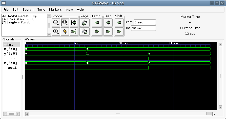
The waveform file is of the type "value change dump" (*.vcd) and can be viewed using the free gtkwave under linux or it's windows equivalent winwave.exe. A screen capture from the above example shows a sequence of inputs (x,y,cin) representing 0+0,5+1 and 5-1 and the corresponding outputs (z,cout). Gtkwave allows you to select which signals to view (->Search->Signal Search Tree) among many other capabilities.
Author: Andrew Morton, University of Waterloo, 2007