CS452 F23 Lecture Notes
Lecture 08 - 03 Oct 2023
1. Interrupts
- see BCM, Ch 6, and ARM Generic Interrupt Controller
- Motivation
- avoid busy waiting for devices
- instead, device signals to get attention
- Interrupts start with signals asserted by devices
- each device defines the signals it can generate
- example: system timer
- four signals, corresponding to 4 System Timer Compare registers (C0-C3)
- when CLO matches value in Cx, signal is asserted
- this is an example of what the ARM refers to as a Shared Peripheral Interrupt (SPI)
- generated by a device, routed to some processor
- there are also Private Peripheral Interrupts (PPI) and Software Generated Interrupts (SGIs)
- SGI generated by software running on some core - can be used to signal other cores
- Interrupts result in an asynchronous exception at a processor
- two signals, FIQ and IRQ, arrive at each processor core
- Reminder: exception vector
- 4 groups 4 entries
- groups identify execution state when exception occurred:
- Current EL with SPO/SPx, Lower EL using 64/32 bit mode
- within each group, entries for different types of exceptions
- synchronous exception (e.g. sys call, memory protectionm, illegal instruction)
- IRQ - asynchronous
- FIQ - asynchronout
- SError - async memory-related exceptions (e.g, parity error, cache write-back error)
- If FIQ or IRQ signal is asserted
- CPU transfers control to exception handler during or after execution of current instruction
- separate handlers for FIQ and IRQ
- Handler
- saves current application context
- figures out the reason for the interrupt
- handle the interrupt
- includes device control and interrupt acknowledgement (more later)
- choose next task to run
- restore chosen task context, return from exception (
eret)
- Masking
- Interrupts can be masked
- IRQ/FIQ still get asserted, but processor ignores them
- DAIF bits in PSTATE
- I is mask for IRQ, F is mask for FIQ
- When exception occurs, interrupts get masked automatically
- kernel can unmask when returning to application by ensuring I and F bits are cleared in
SPSR_EL1register prior to context switch - also possible to unmask within the kernel, but we don’t do this
- kernel can unmask when returning to application by ensuring I and F bits are cleared in
- Interrupts can be masked
1.1. Interrupt Controller
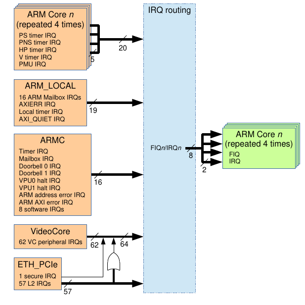
- connects the device signals to FIQ/IRQ at each core
- BCM 2711 has:
- GIC-400
- Legacy Interrupt Controller - we’re not using

Figure 1: Interrupt Controller Overview
- functions of the controller:
- assigns ID to each input signal
- config interrupt from each signal
- enable/disable
- edge-triggered, level-sensitive
- route input signals to outputs
- prioritize interrupts
- manage state of each interrupt
- GIC-400 split into parts
- Distributor (CICD)
- CPU Interface (GICC)
- GICD and GICC each have control registers that kernel can use to control interrupts
GIC_BASE = 0xff840000GICD_BASE = GIC_BASE + 0x1000GICC_BASE = GIC_BASE + 0x2000
- Control Register Maps:
- GICD: ARM Generic Interface Controller, Table 4.1, page 4-75
- GICC: ARM Generic Interface Controller, Table 4.2, page 4-76
- Interrupt State managed by the GIC
- see Section 3.2.4 of ARM Generic Interrupt Controller
- GIC tracks interrupt state along two dimensions
- Pending/Not Pending
- level-sensitive: is the device asserting?
- edge-senstive: has the device asserted?
Active/Not Active - is the CPU handling the interrupt
Not Pending Pending Not Active Inactive Pending Active Active Active+Pending
- Pending/Not Pending
- Inactive->Pending when device asserts interrupt signal
- level-sensitive: pending as long as device signal is asserted
- edge sensitive: pending until interrupt is handled
- Pending->Active+Pending
- for level-sensitive, when CPU reads
GICC_IARto find cause of interrupt
- for level-sensitive, when CPU reads
- Pending->Active
- for edge-triggered, when CPU reads
GICC_IARto find cause of interrupt
- for edge-triggered, when CPU reads
- remove Active state
- when handler reads
GICC_EOIRto notify GICC of end of processing
- when handler reads
1.2. Handling System Timer Interrupts
- Initialization
- Timer has 4 interrupt signals, corresponding to C0-C3
- C0 and C2 reserved by VC, so use on C1 and C3
- BCM, Ch 6 says system timer interrupts are first 4 VC (video core) interrupts
- Interrupt IDs for video core start at 96, so
- C1 interrupt has InterruptID 97
- C3 interrupt has InterruptID 99
- route the interrupt to IRQ on CPU 0
- use
GICD_ITARGETSRn- each register defines targets for 4 interrupts
- use
- make sure IRQ handler is set up in your kernel’s exception vector
- enable the interrupt
- use
GICD_ISENABLERn- 4-byte registers, with 1 bit per InterruptID
- use
- write values into system timer C1/C3 to trigger interrupt assertion at correct time
- Timer has 4 interrupt signals, corresponding to C0-C3
- Handling the Interrupt
- save application context
- read
GICC_IAR- returns interruptID (should be 97/99)!
- sets interrupt state to Active in GIC
- do work
- update value of system timer C1/C3 (why?)
- write InterruptID to
GICC_EOIR- marks interrupt as not active in GIC
- choose next task, restore next task context, return from exception