Cusp Surface Generation using a Least Squares Surface
University of Waterloo
Department
of Computer Science
Project
for
Splines
and Their Uses in Computer Graphics CS 679
by
Paul Gray
Department of Mechanical Engineering
The project
includes the following:
1.
Implementation of the Swept Volumes algorithm.
2.
Development and implementation of a least squares surface fitting scheme
which includes algorithms to generate u and v parameters for the data points and
knot vectors such that the system of equations is guaranteed to contain at least
one point in each knot span to ensure a well-conditioned system. Control points
and knot vectors for non-uniform bspline surfaces (NUBS) are generated for two
tool passes.
3.
A method was developed to intersect the tool pass surfaces with each
other. This was done by forcing the control points to be evenly spaced in the
range and domain in the v direction which corresponds to the tool’s feed
direction. This ensures that the lines perpendicular to that direction on the
two surfaces are planar for any value of v. For a given step in v, a bisection
method with a signed directional distance between the x-z planar curves of each
surface was used to find an intersection point.
4.
If there is more than one intersection point, the program assumes there
are only 2 intersection points and determines which surface is lowest and
selects the intersection point. This is not accurate because it cuts off an edge
of one of the surfaces that it shouldn’t. However, it was done to avoid the
storage and triangulation of multiple isolated patches of varying geometry in
both u and v directions that would be dependent on the geometry of one of two
surfaces.
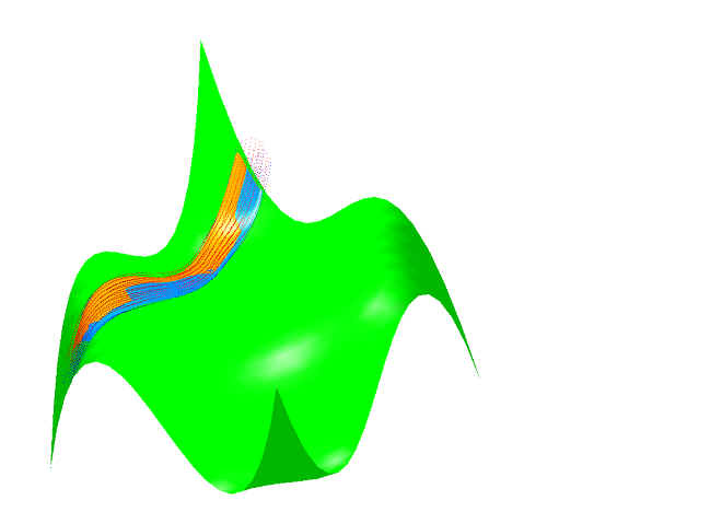
5.
The list of intersection points is converted to clipping parameters in
the u direction for both surfaces which are then rendered.
The software package include the following:
1.
Box zooms, button zooms, panning, dynamic rotation about x, y, and z
axes, a zoom reset button, a rotation and zoom reset button, a program reset
button, a toggle for culling, 3 surface viewing modes (wireframe, flat polygon,
and smooth which uses the actual computed normals of the model and cusp surfaces
at the triangular vertices).
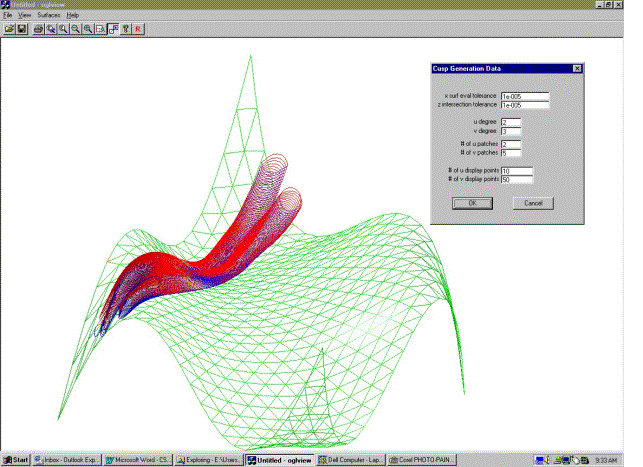
2.
The user may input or select the program defaults for the following
parameters with dialog boxes: the number of display points to be used for
triangulation of the cusp and model surfaces, the degree and the number of
patches to be used in both u and v directions for the surface approximation, the
x and z tolerances to be used to find the clipping intersection points and the
number of intersection points, the number of pseudo inserts to be used to
generate the swept volumes.
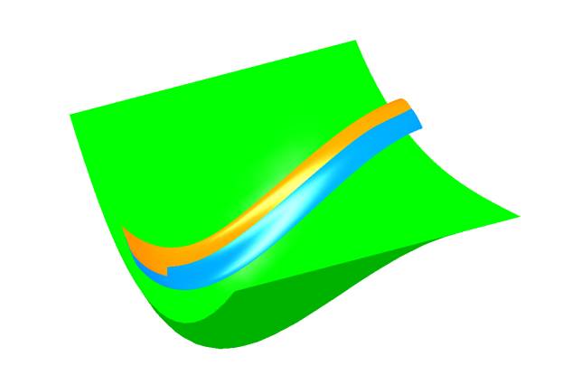
3.
Display selections include any or all of the following: imprint points, imprint lines, triangulation of the imprint
points, the model surface, and the cusp surface.
4.
Lighting, material, and colour, effects were added to aid in the
three-dimensional viewing of the surfaces.
5.
The program can be used to display any number of tool pass imprint points
(however, it will only intersect and generate a cusp surface for the first two
passes).
6.
The graphics on the screen can be saved as a bitmap file and outputted to
the user’s printer of choice.