The project was coded in C (openGL) and uses a Tcl/TK interface. When the
editor is started, an initial surface is loaded from file into the program.
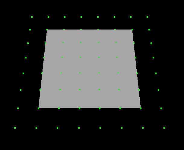
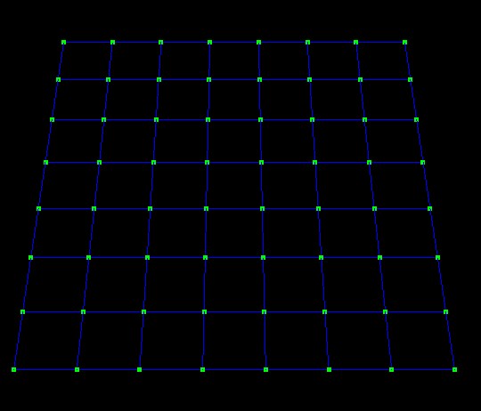
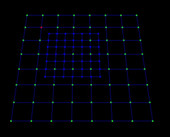
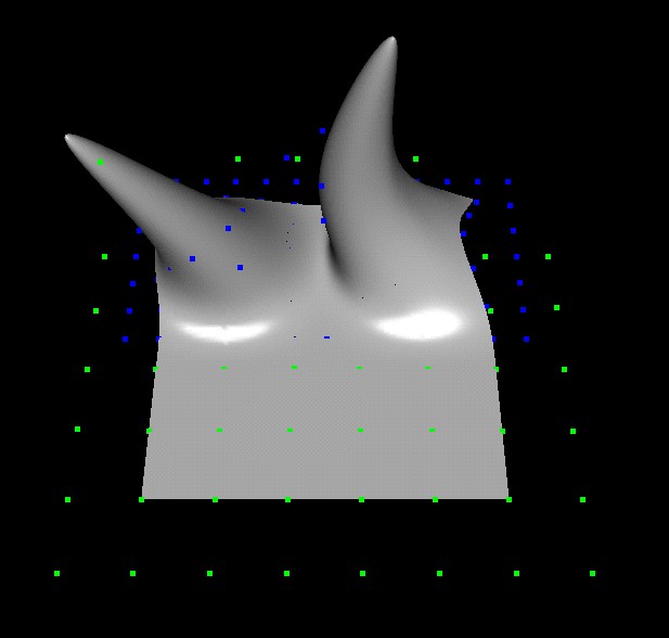
The initial surface consists of 4x4, 8x8, or 12x12 control points (depending on the file loaded) where each point is uniformly spaced and lies on a plane. 
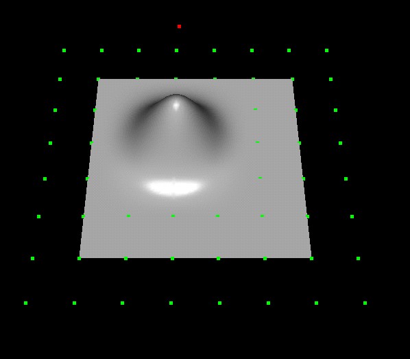
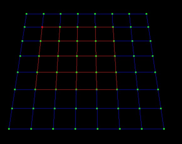
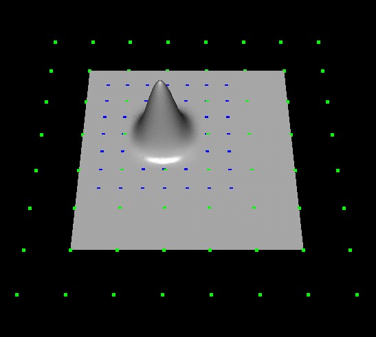
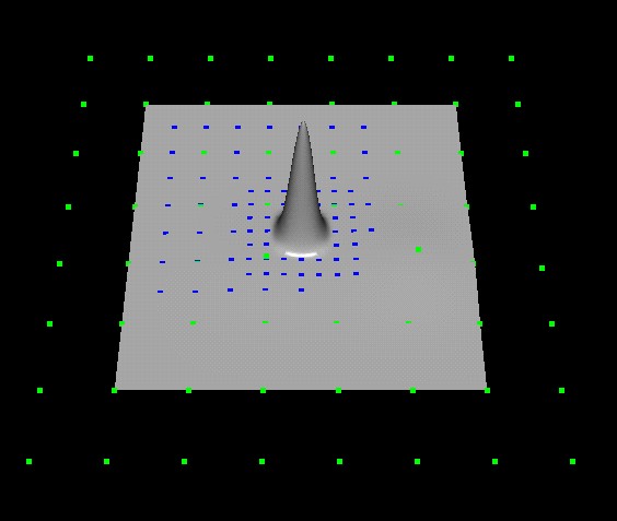
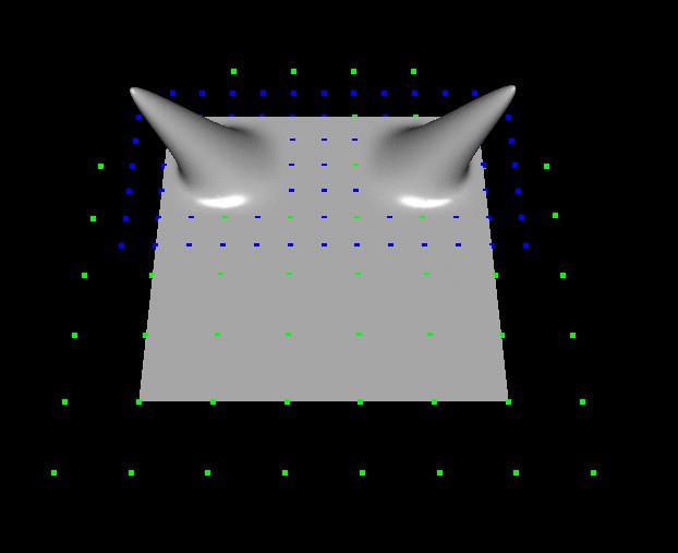
The surface is rendered in patches as a bi-cubic B-spline surface using the gluNurbs function provided in OpenGl. Each patch consists of 16 control points (a 4x4 section). |
![]() |
In order to edit the surface, the control points may be clicked and dragged
using the left mouse button while in manipulation mode. While using edit points on the surface (instead of control points) would have made for a more user friendly interface, time did not permit me to implement this feature. |
![]() |
In order to add an overlay into the control mesh we must first
switch the system into overlay mode. The system then displays the control mesh in a wireframe view. |
![]() |
We select the area where the overlay is to be added by clicking a control point. |
![]() |
We insert the overlay by pressing the "i" button. Note: Since I used overlays consisting of 7x7 control points, only the center overlay control point may be moved during editing. (Moving any another overlay point would result in a tearing of the surface) |
![]() |
In this image no overlays have been used and a single control point has been moved up and away from the plane to create a mound in the surface. We can see that moving this single control point affects a large area of the surface. |
![]() |
In this image a single overlays has been added and a single control point has again been moved up and away from the plane to create a mound in the surface. We can see that moving this single control point affects a smaller area of the surface. |
![]() |
In this image a 2nd overlay has been added over the initial overlay and a single control point has again been moved up and away from the plane to create a mound in the surface. We can see that moving this single control point affects an even smaller area of the surface. |
![]() |
In this image the inital mesh has had 2 overlays added to it and some of the overlay control points have been moved resulting in a new surface. |
![]() |
In this image we see the same mesh with same 2 overlays but some of the base control points have been moved to illustrate the offset rendering. (Note: None of the overlay control points were moved to make this image. |
![]() |